
3D printer server: CR6-SE + Octoprint
3D printing with factory equipment
I bought a Creality CR6-SE 3D printer in November 2020. This was my first own 3D printer. I learned a lot from using it and produced a lot of useful items with it for myself and to my friends.
The basic equipment in this price category only allows local printing, which consists of the following process:
- I create the virtual model of the object to be printed: This is called CAD.
- I export the model to a .stl file.
This file contains information about the shapes and dimensions of the model, but not about the design steps, so the 3D printing professionals use the .stl file format to share their model files with each other. Models found on 3D printing model databases available on the Internet are also to be found in this format. - I load the .stl file into a slicer program.
I used Cura for this printer.
The slicer slices the model into the layers to be printed and creates a .gcode file compiled for the given printer, with given material, with given print settings. This file contains instructions for the printer to execute line by line. - I copy the .gcode file to an SD card.
- I insert the SD card into the 3D printer and select the file for printing on its interface.
- The printer prints the model. Information about the status of the process are provided on it’s screen. I can intervene also only on the physical interface of the printer.
- When the print is ready, I wait for the machine to cool down, then remove the manufactured object and turn off the machine.
The first half of the above steps (1-4) do not even require attendance. And the second half is almost completely replaceable by remote management. In fact, the removal of the object is the only step for which you really need to be physically present, but there are 3D printers that can solve even this step without the physical interaction of the operator.
3D printing from anywhere
I wanted to be able to do the second half of the above steps without having to stay at the printer the whole time.
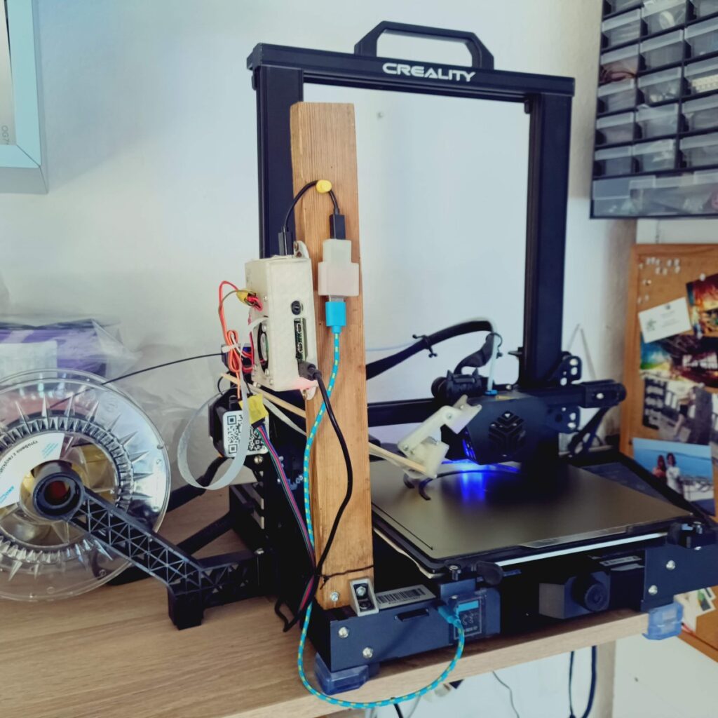
So I put together a print control server that can be managed via the Internet.
For this I used a Raspberry PI 4 computer and a web server called Octoprint.
I installed a camera on the printer so that I could see the printing status remotely via the web server.
I made a relay module with a multiway switch that can be switched to the other state either by hand or by electrical control. With it I can switch the power supply of the 3D printer both via the server, by a program, or by the physical switch in either directions regardless of the actual state.
I installed a series of useful plugins on the web server, which made the system more convenient and safer. There was also a function that I couldn’t solve with a plugin, so I wrote a separate python script for it.
As a result of the improvements, the 3D printer acquired the following new capabilities:
Remote management
With the Octoprint server, I was able to start a print, monitor it and intervene if necessary, regardless of where I am physically. I used the Octoeverywhere cloud app for the access trough the internet: https://octoeverywhere.com/
The process was very convenient that, for example I could go to work in the morning, during the day my colleagues or my boss asked me for something to print, for which I could immediately prepare the model,- then the G code, upload it to the print server, print it out in the afternoon and the next day I could give it to the customer.
Print status notifications
It was during some longer printing that I forgot about my work and looked at the print status less often. Fortunately, I installed the OctoSlack plugin and connected it to the Pushover cloud app.
https://plugins.octoprint.org/plugins/Octoslack/
https://pushover.net/
Pushover is designed to send unique notifications to an app installed on a phone. With the OctoSlack plugin, you can set detailed notifications to a long list of print-related events, but you can also indicate the current status of a print job in % or the number of the completed layers.
Remote control of the main power switch
In order for the server to communicate with the printer, the printer must be turned on. However when switched on, its lights glow and its fans whir. Since my goal was to be able to use the printer at any time, but I didn’t want it to buzz, light up and consume electricity when not in use, I had to make the power supply controllable from software.
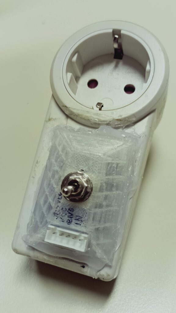
For this, I made a solution that does not require any changes to the internal electronics of the machine: I built a home-made plug-and-socket relay-switch module which i pluged in between the power cable of the 3D printer and the 220V distributor. The relay is connected to the server through the GPIO pins of the PI with a cable.
Perhaps a Wi-Fi capable smart plug would be a more convenient solution for this, but the cable connetion is more error-tolerant because the server can switch the printer’s power source even if the Wi-Fi connection is not available.
The relay installed in the module interrupts both wires, thereby ensuring that the load does not reach the 3D printer when it is switched off. I have used this solution several times when I installed electric relays in devices with plugs, because in this case it can’t be determined which branch of the plug the load goes to.
There is also a toggle switch on the module, which leaves open the possibility of turning the printer on or off by physical intervention. The switch and the relay are connected to each other as a multiway switch circuit, so that any controller (program or person) can switch the socket from any state (on or off) to the other.
The physical switch proved useful for filament replacement and recalibration, because these tasks require physical presence, but not web server functions. The use of the relay was essential for timed printing.
Timed printing
Some larger items took up to 14-15 hours to print. In the studio apartment where we lived, we could not sleep very well next to the working printer, so it became necessary to use the daylight hours as efficiently as possible. However, in the morning, before going to work and having the first coffee, it is not so practical to even bother with starting a print.
For better time management, I came up with the idea of preparing the file for printing the day before, and timing the start of printing for the next morning, around the time we wake up.
For this I used the Print Scheduler plugin created by jneilliii.
https://plugins.octoprint.org/plugins/printscheduler/
The plugin’s settings allow you to run system commands or python scripts and send separate GCODE instructions before and after printing. This was necessary to control the relay module.
The script before the printing turns on the power of the printer, waits for the booting and establishes the USB connection.
The script after the printing monitors the temperature of the hotend and the bed. When both have cooled below 40°C, it turns off the printer.
Safety measures
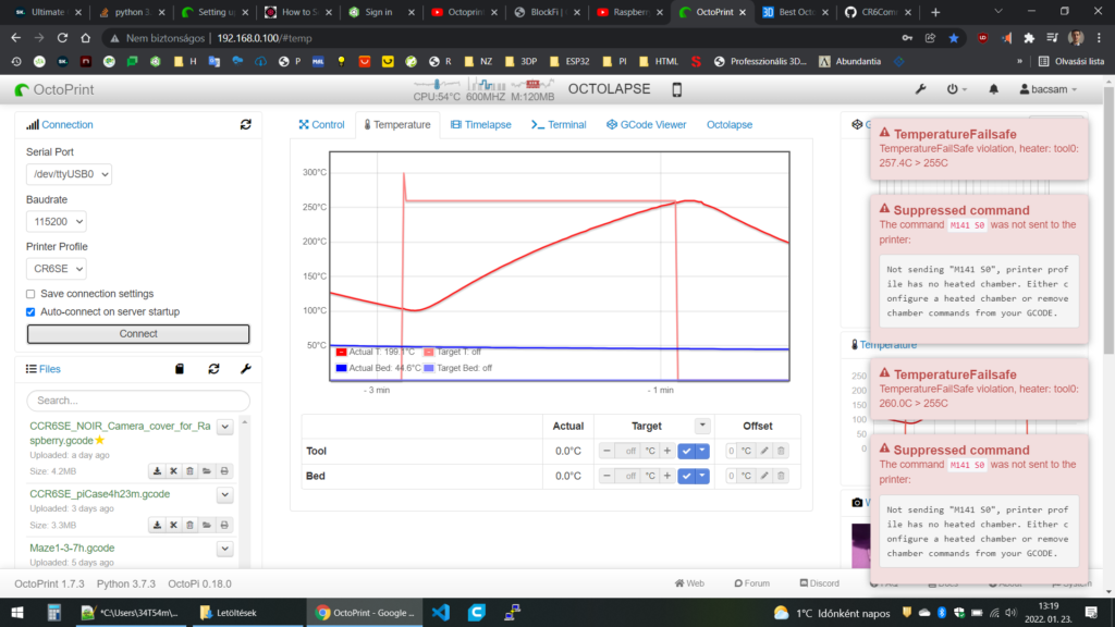
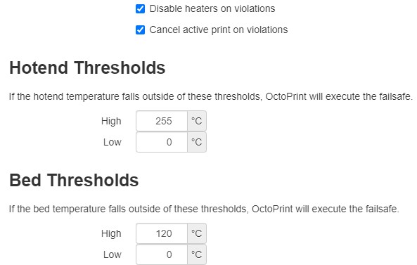
Although the printer’s own controller and Octoprint have their own thermal runaway protection, I decided that another layer of protection for this purpose couldn’t hurt. I used the TemperatureFailsafe plugin and – since I was only printing PLA – I set the maximum temperature to 255°C. I tested its operation with a hot air blower. The test left a mark on the hotend cooling fan, but since it had been whirring for some time anyway, I replaced it.
https://plugins.octoprint.org/plugins/temperaturefailesafe/
The server also sends a pushover notification about
overheating, as it is registered as an error.
Moreover I considered building a remote-controlled fire extinguisher, but in the end I assessed that the false-positive test would cause more damage than the risk of a possible fire.
Part of safe remote use is that I regularly cleaned the machine and its surroundings, stored the filament rolls used as raw material in vapor-proof bags, and was occasionally present during the printing to pay attention to the machine’s noises and possible anomalies.
Additional Plugins
For easier use, I also installed the following plugins:
Detailed Progress
ExcludeRegion
GPIO Control
PrintTimeGenius
TopTemp
UI Customizer
Unique housing, passive and controlled active cooling
I wasn’t satisfied with the case I bought for the Raspberry PI because it didn’t have enough cutouts for the connectors – the accessibility of the camera cable and GPIOs bothered me. That’s why I designed my own housing.
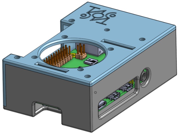
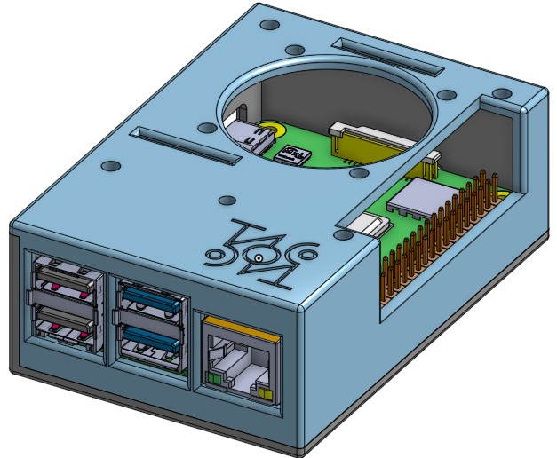
The designed housing consists of only two parts, is easy to print and fits properly to all the connectors.
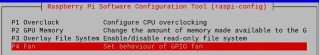
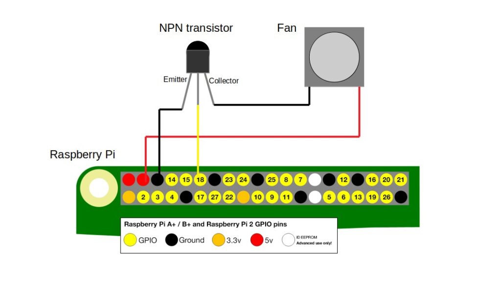
I glued heatsinks to the main chips of the PI, but also gave the device active cooling with a fan. The fan wasn’t loud, but I didn’t want it running 24/7, only when the CPU got too hot. For this, I made the fan controllable from a program using a separate GPIO pin. I didn’t have to write a separate program for this, because the raspi-config utility of the operating system has the necessary function. I chose the minimum possible 60°C to turn on the fan.
The GPIO pins are only for control and can only be loaded with a maximum of 16mA, but the fan consumes approximately 200mA. The 5V Pins, on the other hand, can be drained with up to 2A, although they cannot be controlled from a program. For this reason, I used a mosfet to control the fan.
Due to the environmental conditions and the effectiveness of the passive cooling, the temperature of the processor usually remained around 45-50°C and because of this the fan almost never turned on.
Technical difficulties: Firmware update
The factory firmware of the printer was not suitable for printing by the server. Since I was not satisfied with the firmware installed by the manufacturer anyway and since this was a necessary step for use with the server, I updated the firmware to CR-6 Community Firmware version 6.1. Due to the specific hardware solutions of the printer, this was quite a fiddly operation (two types of specially formatted SD cards, max. 16GB capacity), but it was worth doing it: the developers of Community Firmware fixed the bugs left by the manufacturer and created a much better user interface with more useful functions.
github repository of the Community Firmware:
https://github.com/CR6Community/Marlin/releases
I performed the update steps based on the following video:
Creality CR6 SE Community Firmware UPGRADE : CR6 SE Firmware Update
Technical difficulties: making a USB cable
The PI server communicates with the printer via a USB cable. A USB cable consists of 4 wires: Vcc (power), Data+, Data-, GND (ground). Vcc is used to power the connected peripheral if it does not have its own power supply.
Due to the internal electronic design of the printer, certain components of the printer receive power via the USB cable from the PI even when the printer’s main switch is turned off. In this case, the controller boots, the screen and the object-illuminating LED light up, and the motors beep.
To solve this problem, I made a USB-MicroUSB connector in which the power supply cable is disconnected. The tool solved the problem.