
Wemos Dimmer
This is my first IOT project: a Wi-Fi alarm clock that wakes you up with light. The device is basically a timable lamp with many, many extra functions. I have built this device to learn the functions of an ESP8266 based microcontroller, the Wemos D1 Mini. It enabled a lot of new abilities that the Arduinos I used in my previous projects were not capable of. I later used most of these new abilities listed here in my other, more complex projects.
List of the new funcions
- File management
- Search for a known Wi-Fi network and connect dynamically
- Storing multiple Wi-Fi network access details with a unique encription method
- Automatic time setting: NTP request
- Timed actions
- Web server -> control panel on the microcontroller hosed website
Extras for fun
- Time sync with a client (computer/mobile) or with another iot device
- Temperature measurement
- Display of time, temperature, ip address and rainbow circle arranged into operating states
- Logging different events
- Config panel
- OTA Programming
- Captive portal for AP Mode usage
- Spirit animal generation
File management
While using a computer, file management may seem a basic task, but the Arduinos with the ATmega328P microcontroller used in the previous projects do not use files, and we can only choose from the following types of memory to store data:
Memory type | Writable while the program is running? | Does it retain the data after powering off? | Size |
Program memory – Flash | No | Yes | 32kB |
SRAM | Yes | No | 2kB |
EEPROM | Yes | Yes | 1kB |
The table shows that it is only true for the EEPROM, that it is possible to write while the program is running, and it retains its contents even after switching off. However, its length is only 1kb, it can be written relatively slowly, it can be handled clumsily (the location of the writes must be determined approximately by byte) and its life span is only about 100,000 writes. So the memory is very limited.
In contrast, the Flash memory of the ESP8266 used for this project is divided into several parts and uses the SIPFF or LittleFS file system. The microcontroller has a 4MB Flash memory, which means enormous freedom compared to what is usual with an Arduino. The files are relatively easy to manage, but all file operations are accomplished by special commands, and there are important things to keep in mind, like: A certain write operation sholud be started from the beginning or the end of the file?
After learning the commands for file management, I wrote separate functions to manage data for different purposes. (E.g. file of set timings, file of known Wifi hotspots, etc.)
I thought it was important to talk about this because almost all of the following functions require the file system and its use required specific new knowledge.
There is a great technical documentation of the filesystem on this page: https://arduino-esp8266.readthedocs.io/en/latest/filesystem.html#
Search for Wi-Fi networks and connect dynamically
The Dimmer does not only connect to a single network burned into the program, but stores the name (SSID) and password combinations of known networks in files. Making the unique encryption-decryption of the saved passwords was a particularly interesting task.
When the Dimmer starts, first it scans the Wi-Fi networks in its range as a client – in STA mode.
- If it finds one for which it knows the password, it will connect to it.
- If it doesn’t find any, it becomes a WiFi hotspot itself – switches to AP mode – and you can connect to it with a mobile or computer client.
When connecting to the Dimmer in AP Mode, it will direct you to a captive portal, which is the Known AP setup page. Here you can see the AP-s known by the Dimmer and type in new hotspot names (SSID-s) and their passwords, so the Dimmer will be able to connect to them. When rebooted, the Dimmer will try to connect to the known hotspots in the order shown on the Known AP setup page.
Automatic time setting: NTP request
There is no battery in the Dimmer. When switching off, the set time is forgotten. It annoys me a lot when a digital clock device (microwave, oven) has to be reset using its push buttons after a power loss.
You don’t have to worry about this on the Dimmer, because it adjusts itself automatically.
For automatic time setting, it uses an Internet service specially invented for this purpose: the Network Time Protocol. In a nutshell: With this service any device connected to the Internet can ask the time servers the current time. Our computers and phones all use this built-in to set their system clock.
Web server on a coin-sized piece of electronics
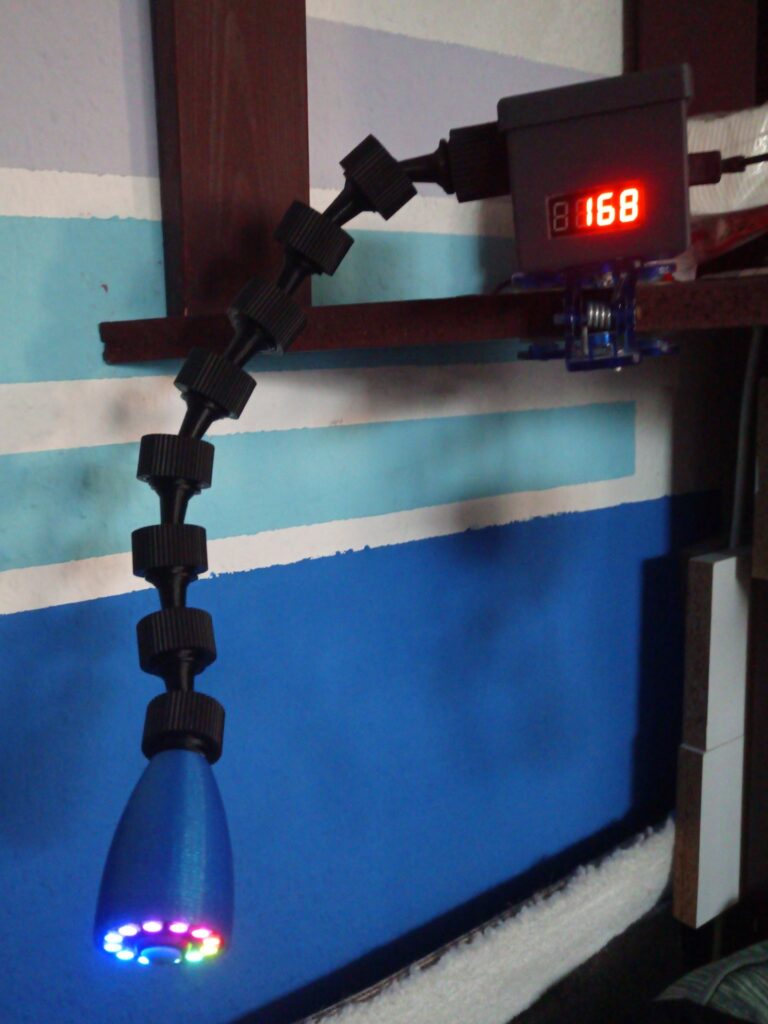
I built the Dimmer with minimal physical interface. There is only one push button on it – even that is only for the purpose to let you stop an active alarm even when groping sleepily. Of course, there are other functions bind to the button as well.
The Dimmer has two displays:
- A NeoPixel LED Ring responsible for the wake-up light.
- A TM1637 hour-minute display.
You don’t even need more than that, because
all of the settings for the alarm times, the known networks and a lot of other extra features can be accessed from a phone or computer, via a browser.
Usage of the Dimmer
How to set an alarm:
While on the same network as the Dimmer, you have to enter the IP address of the device in the search box of the browser. The Dimmer handles the request and sends back the web page required for setting it up – its control interface:
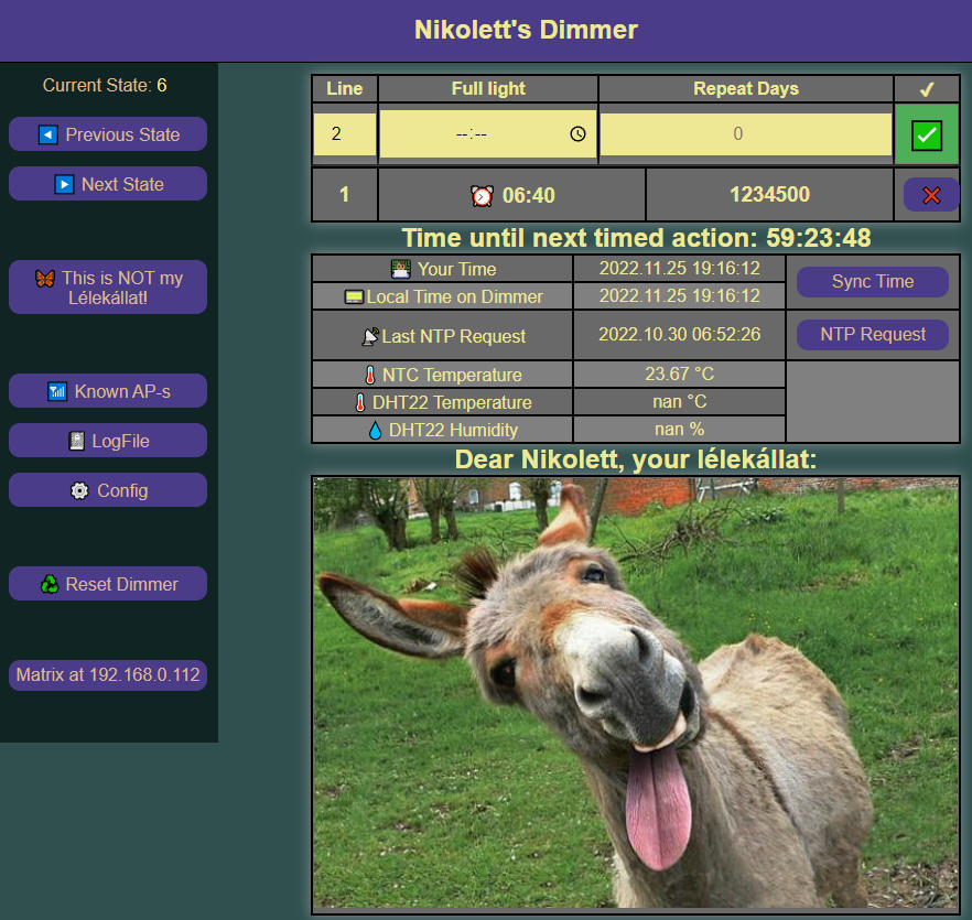
The website gives place of a bunch of functions and it went through many changes as I got to know the HTML, CSS, and JavaScript languages, but I tried to keep it simple and transparent. Its main purpose is still to manage the wake-up times with the panel on the top .
For example, I entered the following values:
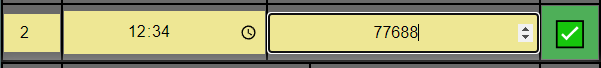
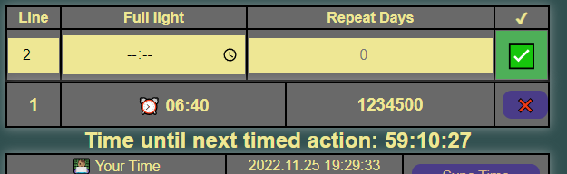
After sending, the Dimmer responds: it updates the stored alerts. It sorts out the meaningless values and the duplicates, and arranges the numbers of the days in a row.
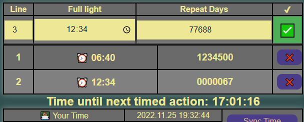
You can overwrite the existing lines by specifiing the number of a new line to a number of an existing one. You can also delete an alarm by the X at the end of its line.
Every time the recorded alarms have changed or when the system time has been corrected (e.g. an NTP request has been made), the Dimmer reads trough the file containing the alarms. It compares the lines in it with the system time and calculates which alarm should take place the soonest.
When it is only half an hour away from the next set time, it switches to wake-up mode: it slowly starts to increase the brightness of the LED Ring. When the set time is reached, the LED Ring plays a circular running light effect with maximum light, which acts like if a light is slowly pulsing. The alarm can be snoozed by a short press of the button and stopped by holding the button.
After stopping the alarm, the Dimmer reads all the alarms again, selects the one which should be executed the soonest and calculates the remaining time until it.
Extras on the main panel
The designated project goals have been realized by the functions described so far, and since this was mainly a learning project, I felt free to wander around among the possibilities provided by the device. I added some functions for unification with my later projects, others for error detection and handling, and some just for fun. I will go through them in the order shown on the website.
Time sync with a client or with another iot device
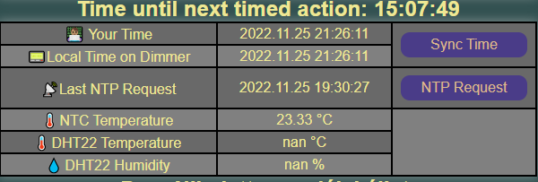
In regard with a later project, I wanted the possibility to set the system time of the microcontroller even without Internet access. This can be done by clicking the SyncTime button and the Dimmer takes over the system time of the phone or computer in our hands and sets it as its own.
NTP requests are made at certain configured intervals or when the Dimmer is restarted, but with this button you can manually instruct the Dimmer to perform an NTP request. An NTP request is made with several attempts. If none of the attempts are successful, the Dimmer does not change its time and tries again after 5 minutes.
A third, automatic option for setting the time is that the Dimmer can request the current time from another IOT device. It only does this if the NTP request failed after a restart. Even if this type of query is successful, the Dimmer will try again the NTP request after 5 minutes.
Thermometer
The temperature and humidity measurements arose regarding my Matrix project, but I only equipped the Dimmer with an NTC thermistor.
Spirit animal

In mobile games, you can come across objects, cards, or figures that can be collected or unlocked in exchange for watching an advertisement. These things usually have no use in the main game and are only present in the game as filler.
I WANTED such a function to the Dimmer! 😀
I imagined that there could be randomly selected funny pictures of animals, of which only one would appear at a time and it would remain on the page until the end of the given active alarm. Then, when an alarm is stopped, a new one would be generated . So if there is one wake-up call per day, a new spirit animal is generated every day, but if we visit the Dimmer website several times on a given day, we will always encounter the same spirit animal.
The 4MB memory of the ESP8266 microcontroller is quite limited for storing images. And I needed a LOT of pictures. The solution is to embed an image found on the Internet in the website, and the Dimmer only stores the url of the image in a text file. So I can choose from hundreds of pictures. The disadvantage of this method is that if I link images from random websites and they are removed from their original location, then they will no longer appear on the Dimmer website.
Extras on the navigation panel
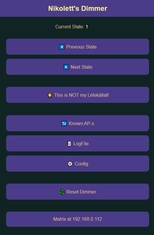
I also made a phone view for the website. In this case, the navigation panel fills the screen. And the main screen slides under the navigation.
Operating States
When the Dimmer is not in the last half hour of the alarm, it works as a simple time display: The number display shows the current hour and minute – the LED ring is not used.
This was pretty boring so I came up with a few more things to display. Switching the new functions back-and-forth made the management of the Dimmer quite chaotic, so I had to use the state machine model and define the following display states:
State | Function of Number display | Function of LED Ring |
1 | Night mode: all displays are dark | |
2 | Hour-minute display | nothing – dark |
3 | Minute – second display | 3 types of pixels circle on the LED Ring like hands on clock face: Red – indicates an hour Green – indicates the minute Blue – indicates seconds When two pixels overlap, the color components are added. Since the LED Ring consists of only 12 pixels, the minute and second colors only change positions every 5 minutes or 5 seconds. The orientation – where the dial should be viewed from – is indicated by white pixels at 12 and 3 o’clock. |
4 | Display of the Dimmer’s IP address | A rainbow circulates on the LED Ring. |
5 | Temperature display | nothing – dark |
6 | Daytime mode: Hour-minute and Temperature display alternating | nothing – dark |
9 | Brightness expressed as a % (0-100) | White light, the brightness of which can be adjusted with the push button. I wanted to use it as a lamp, but in the end I removed this function because I didn’t like the color of the light and it was inconvenient to handle. |
240 | Start of alarm, Hour – minute flashes | from a dark state to increasingly stronger blue light |
241 | After the wake-up time, the hour and minute flashes | The pixels flash one after the other with 100% light and then 0%, around and around, like a running light. |
254 | displaying the word OTA | nothing – dark |
255 | displaying the word OTA | nothing – dark |
The top two buttons of the website’s navigation panel allow you to move between the first six operating states.

You can also move between operating states with the physical button:
- Short button press: switching between day and night modes (1-6)
- Press and hold: switch to the next operating mode.
More buttons in the navigation panel
Pressing the spirit animal button selects a new spirit animal.
The three buttons below lead to different interfaces, the tasks of which are:
| Known AP-s | Management of the known Wi-Fi hotspots: add, delete. |
| LogFile | For debugging, Dimmer writes certain activities to a file, which can be read at the linked location. For ease of reading, I used a text solution here. Some example: 1970.00.00 00:00:00 Restarting… |
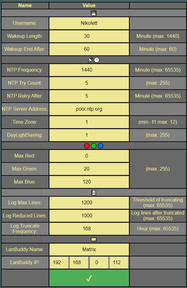
| Config | I found it necessary to write the values of some rarely changing variables into a file. I made a separate page for easy handling of these. |
The Reset Dimmer button resets the Dimmer. 🙂
And the bottom button is a link to a device called Matrix.
Config
OTA Programming
OTA – Over The Air stands for a method with which it is possible to program a microcontroller through Wi-Fi. It is useful when the microcontroller is hard to reach, or when you want to program several microcontrollers at once.
A small technical difficulty: At some point of the development I used interruptive tickers for timing of different functions. The OTA Update fails if an interruptive ticker is still active while uploading the new code. That is why I made the 255 OTA state: to detach the tickers before uploading the new code, and the 254 state: to reattach the tickers before returning to normal operation.
Summary
The Dimmer is the result of a several months-long learning process. Sometimes I left it half way, then expanded it further. It served as a wake-up clock for three years, although sometimes even when I became more alert to its light, I tended to rest longer and waited for the phone’s alarm to help me out of bed.
I used the functions written and tested at the Dimmer in several of my later projects.