
IOT Irrigation System - QT
Why did I make it?
At a time, my girlfriend and her friend were excited about the idea of growing their own food. My parents’ somewhat abandoned plot of land was at their disposal for the idea. The plot had electricity, a well and a pump, so we were able to do the watering of the plants with a garden hose and a sprinkler. To water the plants only a switch needed to be turned on. Since we didn’t want to go out every day to turn on a switch, we needed a timer of the power switch. In the first year, we used a mechanical timer available in a store for this purpose. The tool fulfilled its basic purpose, but there were anomalies:
- the pipe got blocked and the pump stretched it apart at the connection
- after a power outage, the timer started watering a few hours later, which annoyed the neighbor
- there was a severe drought for several weeks and the pump sucked out all the water and ran dry
- one of the pump’s rubber seals broke and could not produce enough pressure for the water to reach the vegetable garden.
These problems made necessary a device that can detect and indicate emerging errors, so that we can deal with them quickly. I created a pump controller for this task and named it QT (‘QT’ is a funny spelling of the Hungarian word ‘kút’ which means ‘well’). The reason for the choice of name is that the physical location of the controller would originally have been directly next to the well, so this is a well-controller.
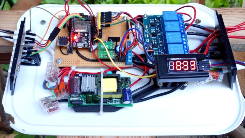
Until the writing of this description, this is my most complex microcontroller project. During its development, I used features learned/developed in several of my previous IOT projects.
What can the QT do?
As with all my IOT projects connected to cloud applications, the main function is: remote control/management. In the case of the QT, it is more important than before to execute the timings correctly and to indicate their success or the errors that have occurred.
For its operation, it uses the capabilities of the Dimmer, performs NTP requests, and also uses three web applications: Firebase, Pushover and ThingSpeak.
It controls six types of sensors and four relays for its activities.
What does the QT control?
It controls the operation of the pump
I applied the timing capability of the Dimmer with small modifications to the switching of the pump.
It controls the path of water
The basic task is to water the vegetable garden, but there is also a birdbath on the plot made for bird photography, which tends to dry out in the summer heat. In order to be able to water the vegetable garden and fill the birdbath using one single pump, I built a custom 3d printed Y-distributor into a section of the pipeline, equipped with solenoids (electric taps). The QT controller can determine the direction of the water flow by switching the solenoids.
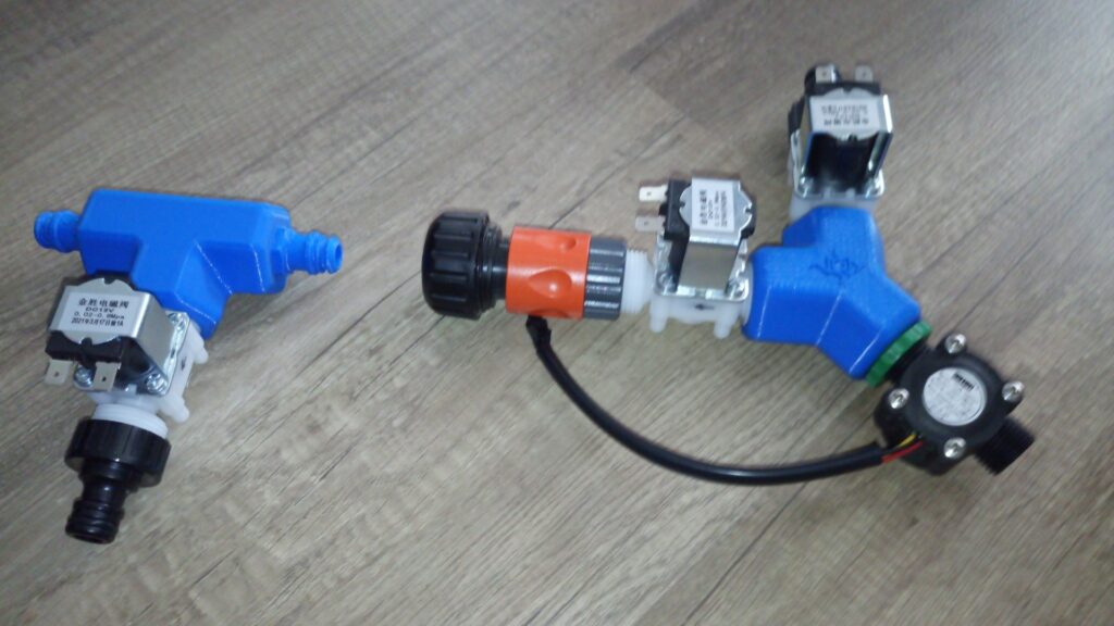
In winter, it controls a low-power water heater
The best time to use the birdwatching hide is in winter, because then you can accustom the birds in front of the camera by feeding and drinking them. In winter, however, the drinking water tends to freeze. But, with a low-power heater, you can – at least partially – melt the ice in the drinker so that the birds (and the martens, foxes, cats, mice, squirrels) can drink from it.
What does the QT sense?
I equipped the QT controller with the following sensors:
- YF S201 flow sensor
- Water level indicator by float switches (2pcs)
- NTC Thermistor – thermometer
- RTC Module – Real Time Clock with a battery and a thermometer
- Rain sensor
- Soil moisture sensor
Sensing the flow
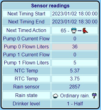
Irrigation can be called successful if the water reaches the crops from the well. To detect this, I used a YF S201 type flow sensor, which generates voltage pulses at its output when liquid flows through it. The flow rate and the amount of water pumped out since the given time can be calculated from the number of pulses received during the given time unit. Depending on the length of the timer, we irrigated with approximately 150-200 L of water during one sprinkling.
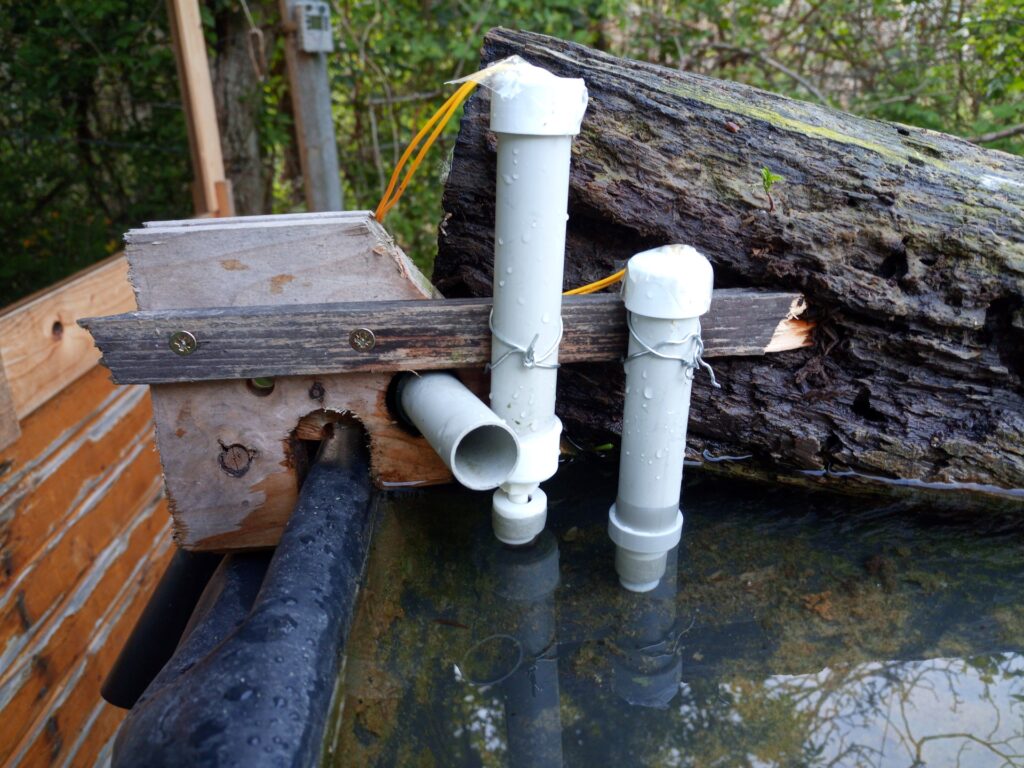
Sensing the water level of the birdbath
I made a water level indicator consisting of two float switches.
Its possible states are:
Lower sensor position | Upper sensor position | Meaning | Case number |
Dropped | Dropped | The birdbath is empty. | 0 |
Floats | Dropped | The birdbath is “half” full. | 1 |
Floats | Floats | The birdbath is full. | 2 |
Dropped | Floats | One of the sensors is faulty. | 3 |
The QT controller only starts filling the drinker when it is empty. And when it’s full, it won’t fill it even more.
Sensing the temperature
The primary thermometer is the NTC Thermistor dipped into the water. Whether the water heater should turn on or off depends on the measured value.
The QT controller got equipped with a DS3231 type Real Time Clock module, which, thanks to its internal battery, can keep the current time for months even when turned off. The clock module also has its own thermometer. The module is located next to the controller in a closed box, so it measures the temperature inside housing.
Sensing the rain
On an experimental basis, I placed a low budget resistive rain sensor next to the controller. In the summer, it signaled passing storms quite reliably. However, with the arrival of autumn wet weather, it is not really possible to distinguish the moisture coming from rain and from condensation.
Sensing the soil moisture
I connected a capacitive sensor, similar to the rain sensor, to the controller in order to verify the occurrence of rain from the wetting of the ground. The measurement data are quite chaotic, with a very large standard deviation. At most, whether the ground is wet or not can be guessed by the fact that in dry weather the values fluctuate by 10-20% of the measurement range, and in rainy weather by 70-80% of the entire range.
What does the QT indicate?
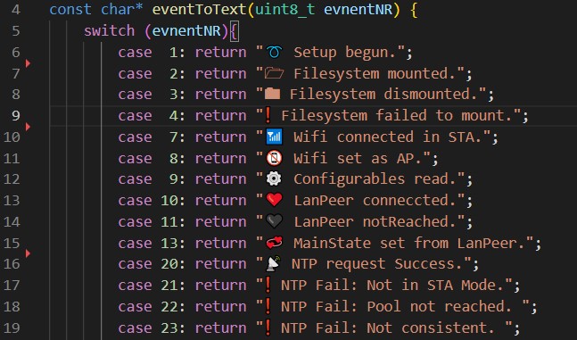
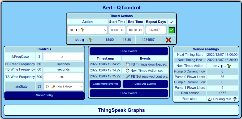
I defined 85 different events to uniformly indicate the states and activities of the QT controller. They describe everything that can happen to the controller: communication activities, changes to settings, switching between operating states, results of timed activities, errors. To count the possible events, I started from the operating states defined at the Dimmer and the events recorded in the log. I kept the amount of data required to record an event as small as possible: The QT controller only registers the time and number of the event. To do this, it only needs 5 bytes per event. The textual interpretation of the events is only done at their display.
In addition to events, the QT controller registers some status indicators to inform.
How does it communicate?
The QT controller establishes data connections with the following cloud applications:
Cloud application | Content |
FireBase | Downloads control variables, timings, config. Uploads events and measurements. |
ThingSpeak | Uploads sensor data |
Pushover | Sends certain events |
Firebase
Firebase operates the central database of the QT controller and the website serving as its management interface. Similar to how the ESP 32 Camera works: the QT controller reads Control variables and timings at regular intervals. If an event occurs – whether the FireBase Control values change or something happens locally – it is handled and added to the list of events stored in the cloud.
If a given event could not be uploaded to the cloud – due to a network error or any other reason – it will be stored locally in a file, and later, when the cloud database is available again, the locally stored events will be uploaded and deleted from the local memory.
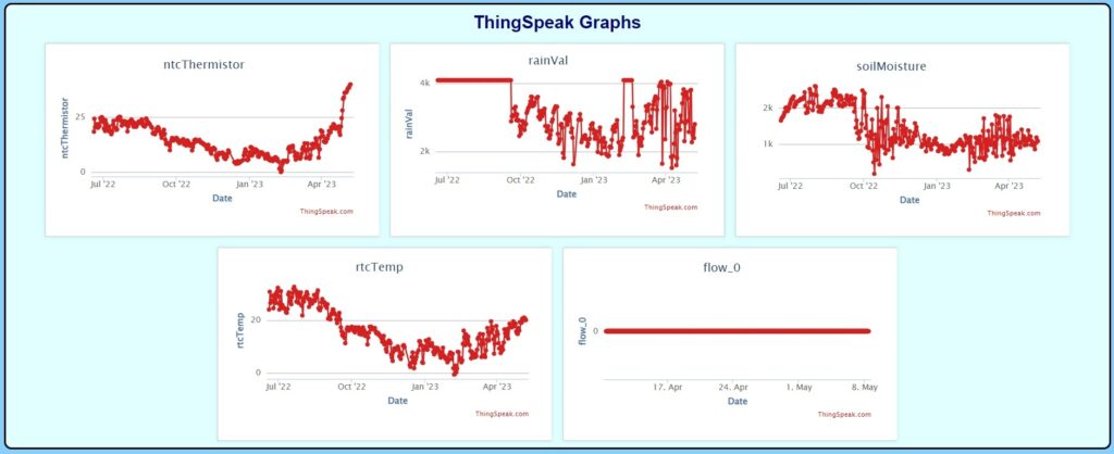
ThingSpeak
I wanted to graph the measurements of the thermometers and the two rain-related sensors. FireBase would have been perfectly suitable for storing the measurements, but to display them on gauges or graphs I would have had to write additional code, which I did not feel like doing, so for this purpose I used the storage and display options provided by ThingSpeak instead.
Pushover
The task of Pushover is the same as in the case of the 3D printer: With the service, the QT controller sends push messages to phone about the occurrences of certain events. I didn’t want to receive push messages about each and every event, but only about those that are critical to the operation:
- About changes in operating states related to the pump and the heater
- About the occurrence of NTP requests
- About restarts.
Local usage
During the gardening works it would not be practical if the pump could only be switched on/off from a phone/laptop. For this purpose, there is also a push button on the controller, which can be used to switch the controller between the main operating states. The feedback is provided by a TM1637 hour-minute display. Of course, the QT controller also registers and indicates the events of the push-button use.
Summary, final words
Thanks to the QT controller, the crops received a sufficient amount of water throughout the summer, despite the fact that the whole of Europe was hit by a drought not seen in many years. With its help, we were able to notice and deal with the pump’s faults in time. Also, we were able to react remotely to the slowly draining water volume of the well: we set the watering for a shorter time.
During the development of the controller I gained a lot of new knowledge and had to deal with a large pile of errors. Unfortunately, I would not call the project finished, because although it achieved the above goals, I did not manage to solve certain problems in the end, and after several months of development and the change in my life situation, I no longer felt like continuing. I see a chance to return to it in the future, but right now there are more important things to do around me…